扩展算子规则
扩展算子的实现可以在Caffe、TensorFlow、MindSpore深度学习框架中实现,扩展算子中的第一种是基于Caffe框架进行扩展实现的,如ROIPooling、PSROIPooling、Normalize和Upsample层等,因此有公开的prototxt标准定义。而扩展算子中的第二种并不是在Caffe框架下实现的,对于这类网络中的自定义算子,也需要给出prototxt的标准定义,用于在prototxt中定义网络中相应的算子。
Reverse
在指定的轴上反序,如输入为[1,2,3],其反序为[3,2,1]。
算子定义如下:
- 在LayerParameter中添加ReverseParameter
message LayerParameter { ... optional ReverseParameter reverse_param = 157; ... } - 定义ReverseParameter类型以及属性参数
message ReverseParameter{
  repeated int32 axis = 1;
}
ROIPooling
在目标检测算法中,region proposal产生的ROI大小不一,而分类网络的FC层要固定的输入,所以ROIPooing起到一个连接作用。
ROIPooling层为Faster RCNN网络中用于将不同图像经过卷积层后得到的feature map进行维度统一的操作,输入为一个feature map以及需要从中提取的ROI框坐标值,输出为一个维度归一化的feature map。
ROIPooling层需要对caffe.proto文件进行扩展,定义ROIPoolingParameter,扩展方式如下所示,定义的参数包括:
- spatial_scale,即输入feature map与原始图片的尺寸比例,用于转换ROI的坐标,因为ROI坐标是在原图尺寸上的。
- pooled_h、pooled_w,输出feature map在spatial维度上h和w的大小。
- 在LayerParameter中添加ROIPoolingParameter
message LayerParameter { ... optional ROIPoolingParameter roi_pooling_param = 161; ... } - 定义ROIPoolingParameter类型以及属性参数
message ROIPoolingParameter {
    required int32 pooled_h = 1;
    required int32 pooled_w = 2;
    optional float spatial_scale = 3 [default=0.0625];
    optional float spatial_scale_h = 4;
    optional float spatial_scale_w = 5;
}
基于上述原则,ROIPooling层在prototxt中定义的代码样例如下:
layer {
name: "roi_pooling"
type: "ROIPooling"
bottom: "res4f"
bottom: "rois"
bottom: "actual_rois_num"
top: "roi_pool"
roi_pooling_param {
  pooled_h: 14
  pooled_w: 14
  spatial_scale:0.0625
  spatial_scale_h:0.0625
  spatial_scale_w:0.0625
  }
}
PSROIPooling
PSROIPooling层的操作与ROIPooling层类似,不同之处在于不同空间维度输出的图片特征来自不同的feature map channels,且对每个小区域进行的是Average Pooling,不同于ROIPooling的Max Pooling。
对于一个输出k*k的结果,不同空间维度的特征取自输入feature map中不同的组,即将输入的feature map均匀分为k*k组,每组的channel数与输出的channel一致,得到上述输出。
PSROIPooling层需要对caffe.proto文件进行扩展,定义PSROIPoolingParameter,扩展方式如下所示,定义的参数包括:
- spatial_scale,即输入feature map与原始图片的尺寸比例。
- output_dim,输出feature map的channel。
- group_size,输出的spatial维度,即上述的k。
- 在LayerParameter中添加PSROIPoolingParameter
message LayerParameter { ... optional PSROIPoolingParameter psroi_pooling_param = 207; ... } - 定义PSROIPoolingParameter类型以及属性参数
message PSROIPoolingParameter {
   required float spatial_scale = 1;
   required int32 output_dim = 2; // output channel number
   required int32 group_size = 3; // number of groups to encode position-sensitive score maps
}
基于上述原则,PSROIPooling层在prototxt中定义的代码样例如下:
layer {
  name: "psroipooling"
  type: "PSROIPooling"
  bottom: "some_input"
  bottom: "some_input"
  top: "some_output"
  psroi_pooling_param {
    spatial_scale: 0.0625
    output_dim: 21
    group_size: 7
  }
}
Upsample
Upsample层为Pooling层的逆操作,其中每个Upsample层均与网络之前一个对应大小输入、输出Pooling层一一对应,完成feature map在spatial维度上的扩充。
Upsample层需要对caffe.proto文件进行扩展,定义UpsampleParameter,扩展方式示例如下所示。 定义的参数包括stride,即输出与输入的尺寸比例,如2。
- 在LayerParameter中添加UpsampleParameter
message LayerParameter { ... optional UpsampleParameter upsample_param = 160; ... } - 定义UpsampleParameter类型以及属性参数
message UpsampleParameter{
    optional float scale = 1[default = 1];
    optional int32 stride = 2[default = 2];
    optional int32 stride_h = 3[default = 2];
    optional int32 stride_w = 4[default=2];
}
基于上述原则,Upsample在prototxt中定义的代码样例如下:
layer {
    name: "layer86-upsample"
    type: "Upsample"
    bottom: "some_input"
    top: "some_output"
    upsample_param {
		scale: 1
                stride: 2
    }
}
Normallize
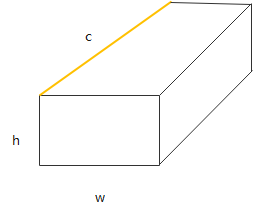
Normalize层为SSD网络中的一个归一化层,主要作用是将空间或者通道内的元素归一化到0到1之间,其进行的操作为对于一个c*h*w的三维tensor,输出是同样大小的tensor,其中间计算为每个元素以channel方向的平方和的平方根求normalize,其具体计算公式为:

其中分母位置的平方和的累加向量为同一h与w位置的所有c方向的向量,如图1中的橙色区域。
经过上述计算归一化后,再对每个feature map做scale,每个channel对应一个scale值。
Normalize层需要对caffe.proto文件进行扩展,定义NormalizeParameter,扩展方式如下所示。定义的参数包括:
- across_spatial参数表示是否对整个图片进行归一化,归一化的维度为:1 x c x h x w,否则对每个像素点进行归一化:1 x c x 1 x 1。
- channels_shared表示scale是否相同,如果为true,则scale都是一样的,否则对于channel一样,对不同channel像素点是不一样的,默认为True。
- eps防止normalize过程中除以0的一个很小数值,默认为1e-10,可配置。
normalize的计算公式转换为:

算子定义如下:
- 在LayerParameter中添加NormalizeParameter
message LayerParameter { ... optional NormalizeParameter norm_param = 206; ... } - 定义NormalizeParameter类型以及属性参数
message NormalizeParameter {
  optional bool across_spatial = 1 [default = true];
  // Initial value of scale. Default is 1.0 for all
  optional FillerParameter scale_filler = 2;
  // Whether or not scale parameters are shared across channels.
  optional bool channel_shared = 3 [default = true];
  // Epsilon for not dividing by zero while normalizing variance
  optional float eps = 4 [default = 1e-10];
}
基于上述原则,Normalize在prototxt中定义的代码样例如下:
layer {
  name: "normalize_layer"
  type: "Normalize"
  bottom: ""some_input"
  top: "some_output"
  norm_param {
    across_spatial: false
    scale_filler {
      type: "constant"
      value: 20
    }
    channel_shared: false
  }
}
Reorg
Reorg算子在昇腾AI处理器内部以PassThrough算子呈现,将通道数据转移到平面上,或反过来操作。
PassThrough层为Yolo v2中的一个自定义层,由于Yolo v2并不是使用Caffe框架实现,因此对于该层没有标准的定义。该层实现的功能为将feature map在spatial维度上的数据展开到channel维度上,原始在channel维度上连续的元素在展开后的feature map中依然是连续的。
算子定义如下:
- 在LayerParameter中添加ReorgParameter
message LayerParameter { ... optional ReorgParameter reorg_param = 155; ... } - 定义ReorgParameter类型以及属性参数
message ReorgParameter{
    optional uint32 stride = 2 [default = 2];
    optional bool reverse = 1 [default = false];
}
基于上述原则,Reorg在prototxt中定义的代码样例如下:
layer {
    bottom: "some_input"
    top: "some_output"
    name: "reorg"
    type: "Reorg"
    reorg_param {
        stride: 2
    }
}
Proposal
Proposal算子根据rpn_cls_prob的foreground,rpn_bbox_pred中的bounding box regression修正anchors获得精确的proposals。
具体可以分为3个算子decoded_bbox、topk和nms,实现如图2所示。
算子定义如下:
- 在LayerParameter中添加ProposalParameter
message LayerParameter { ... optional ProposalParameter proposal_param = 201; ... } - 定义ProposalParameter类型以及属性参数
message ProposalParameter {
    optional float feat_stride = 1 [default = 16];
    optional float base_size = 2 [default = 16];
    optional float min_size = 3 [default = 16];
    repeated float ratio = 4;
    repeated float scale = 5;
    optional int32 pre_nms_topn = 6 [default = 3000];
    optional int32 post_nms_topn = 7 [default = 304];
    optional float iou_threshold = 8 [default = 0.7];
    optional bool output_actual_rois_num = 9 [default = false];
}
基于上述原则,Proposal在prototxt中定义的代码样例如下:
layer {
name: "faster_rcnn_proposal"
type: "Proposal"                  // 算子Type


bottom: "rpn_cls_prob_reshape"
bottom: "rpn_bbox_pred"
bottom: "im_info"
top: "rois"
top: "actual_rois_num"        // 增加的算子输出
  proposal_param {

  feat_stride: 16
  base_size: 16
  min_size: 16
  pre_nms_topn: 3000
  post_nms_topn: 304
  iou_threshold: 0.7
  output_actual_rois_num: true
  }
}

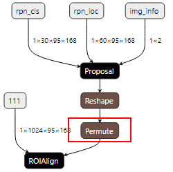
如果用户的网络模型中存在“Proposal+ROIAlign+业务算子”相关的网络结构,由于Proposal算子的输出为3维,而ROIAlign算子的rois是2维,因此需要在Proposal算子后面增加Reshape算子,用来改变Tensor shape,然后作为ROIAlign的输入。但该场景下输入给ROIAlign算子的rois框数据,坐标排序混乱,不符合ROIAlign算子的要求。
基于上述问题,需要在Reshape算子后再增加Permute算子,进行转置之后,再次输出的数据符合ROIAlign算子的要求。
修改后的网络结构样例如下:

对应修改后的prototxt中代码样例如下:
layer {
  name: 'proposal'
  type: 'Proposal'
  bottom: 'rpn_cls'
  bottom: 'rpn_loc'
  bottom: 'img_info'
  top: 'roi_proposal'
  proposal_param {
    feat_stride: 16
    pre_nms_topn: 1000
    post_nms_topn: 16
    nms_thresh: 0.7
    base_size: 16
    min_size: 8
    ratio: [0.5, 1.0, 2.0]
    scale: [32, 64, 128, 256, 512]
  }
}
layer {
    name: "Reshape1"
    type: "Reshape"
    bottom: "roi_proposal"
    top: "roi_proposal_reshape"
    reshape_param {
      shape {
        dim: 5
        dim: 16
      }
    }
}
layer {
    name: "Permute1"
    type: "Permute"
    bottom: "roi_proposal_reshape"
    top: "roi_proposal_permute"
	permute_param {
		order: 1
		order: 0
	}
}
layer {
  name: "align"
  type: "ROIAlign"
  bottom: "111"
  bottom: "roi_proposal_permute"
  top: "align"
  roi_align_param {
    pooled_w: 14
    pooled_h: 14
    spatial_scale: 0.0625
  }
}
ROIAlign
ROIAlign是在Mask-RCNN论文里提出的一种区域特征聚集方式,与ROIPooling算法进行改进:用双线性插值替换ROIPooling操作中两次量化,以解决ROIPooling造成的区域不匹配的问题,提高检测准确性。
ROIAlign算子是从feature map中获取ROI(range of interest),分为pooled_w x pooled_h个单元格,每个单元格均分为sampling_ratio*sampling_ratio个小方格,每个小方格的中心点就是采样点。如图3所示,虚线部分表示feature map,实线表示ROI,这里将ROI切分成2x2的单元格。如果采样点数是4,则首先将每个单元格子均分成四个小方格(如红色线所示),每个小方格中心就是采样点。由于采样点的坐标通常是浮点数,所以需要对采样点像素进行双线性插值(如图3中的四个箭头所示),就可以得到该像素点的值了。然后对每个单元格内的四个采样点取均值,就可以得到最终的ROIAlign的结果。
算子定义如下:
- 在LayerParameter中添加ROIAlignParameter
message LayerParameter { ... optional ROIAlignParameter roi_align_param = 154; ... } - 定义ROIAlignParameter类型以及属性参数
message ROIAlignParameter {
  // Pad, kernel size, and stride are all given as a single value for equal
  // dimensions in height and width or as Y, X pairs.
  optional uint32 pooled_h = 1 [default = 0]; // The pooled output height
  optional uint32 pooled_w = 2 [default = 0]; // The pooled output width
  // Multiplicative spatial scale factor to translate ROI coords from their
  // input scale to the scale used when pooling
  optional float spatial_scale = 3 [default = 1];
  optional int32 sampling_ratio = 4 [default = -1];
  optional int32 roi_end_mode = 5 [default = 0];
}
根据上述类型以及属性用户可以自定义prototxt。
ShuffleChannel
ShuffleChannel是把channel维度分为[group, channel/Group],然后再在channel维度中进行数据转置[channel/Group,group]。
例如对于channel=4,group=2,则执行此算子后,就是把channel[1]、channel[2]的数据交换位置。
算子定义如下:
- 在LayerParameter中添加ShuffleChannelParameter
message LayerParameter { ... optional ShuffleChannelParameter shuffle_channel_param = 159; ... } - 定义ShuffleChannelParameter类型以及属性参数
message ShuffleChannelParameter{
    optional uint32 group = 1[default = 1]; // The number of group
}
基于上述原则,ShuffleChannel在prototxt中定义的代码样例如下:
layer {
  name: "layer_shuffle"
  type: "ShuffleChannel"
  bottom: "some_input"
  top: "some_output"
  shuffle_channel_param {
    group: 3
  }
}
Yolo
YOLO算子出现在YOLO V2网络,且目前仅在YOLO V2、V3网络中使用,对数据做sigmoid和softmax操作。
- 在YOLO V2中,根据background和softmax的参数,有4种场景:
- background=false,softmax=true,
- background=false,softmax=false,
- background=true,softmax=false,
- background=true,softmax= true,
- 在YOLO V3中,只有一种场景:对(x,y,h,w)中的(x,y)做sigmoid,对b做sigmoid,对classes做sigmoid。
输入数据格式为Tensor(n, coords+backgroup+classes,l.h,l.w),其中n是anchor box的数量,coords表示x,y,w,h。
算子定义如下:
- 在LayerParameter中添加YoloParameter
message LayerParameter { ... optional YoloParameter yolo_param = 199; ... } - 定义YoloParameter类型以及属性参数
message YoloParameter {
  optional int32 boxes = 1 [default = 3];
  optional int32 coords = 2 [default = 4];
  optional int32 classes = 3 [default = 80];
  optional string yolo_version = 4 [default = "V3"];
  optional bool softmax = 5 [default = false];
  optional bool background = 6 [default = false];
  optional bool softmaxtree = 7 [default = false];
}
基于上述原则,Yolo在prototxt中定义的代码样例如下:
layer {
	bottom: "layer82-conv"
	top: "yolo1_coords"
	top: "yolo1_obj"
	top: "yolo1_classes"
	name: "yolo1"
	type: "Yolo"
	yolo_param {
		boxes: 3
		coords: 4
		classes: 80
		yolo_version: "V3"
		softmax: true
		background: false
    }
}
PriorBox
根据输入的参数,生成prior box。
下面以conv7_2_mbox_priorbox为例,根据对应的参数生成prior box的数量。定义如下:
layer{
    name:"conv7_2_mbox_priorbox"
    type:"PriorBox"
    bottom:"conv7_2"
    bottom:"data"
    top:"conv7_2_mbox_priorbox"
    prior_box_param{
        min_size:162.0
        max_size:213.0
        aspect_ratio:2
        aspect_ratio:3
        flip:true
        clip:false
        variance:0.1
        variance:0.1
        variance:0.2
        variance:0.2
        img_size:300
        step:64
        offset:0.5
    }
}
- 宽高都为minsize生成prior box。
- 如果存在max_size,则用sqrt(min_size*max_size)确定宽高生成一个框(约束,max_size>min_size)。
- 根据aspect_ratio(如定义所示aspect_ratio为2,3,flip是true,自动添加aspect_ratio=1/2、1/3),生成对应的prior box。
因此,num_priors(prior box的数量)= min_size的数量+aspect_ratio的数量(这里为4)*min_size的数量(这里为1)+max_size的数量 (max_size的数量和min_size的数量一一对应)。
算子定义如下:
- 在LayerParameter中添加PriorBoxParameter
message LayerParameter { ... optional PriorBoxParameter prior_box_param = 203; ... } - 定义PriorBoxParameter类型以及属性参数
message PriorBoxParameter {
  // Encode/decode type.
  enum CodeType {
    CORNER = 1;
    CENTER_SIZE = 2;
    CORNER_SIZE = 3;
  }
  // Minimum box size (in pixels). Required!
  repeated float min_size = 1;
  // Maximum box size (in pixels). Required!
  repeated float max_size = 2;
  // Various of aspect ratios. Duplicate ratios will be ignored.
  // If none is provided, we use default ratio 1.
  repeated float aspect_ratio = 3;
  // If true, will flip each aspect ratio.
  // For example, if there is aspect ratio "r",
  // we will generate aspect ratio "1.0/r" as well.
  optional bool flip = 4 [default = true];
  // If true, will clip the prior so that it is within [0, 1]
  optional bool clip = 5 [default = false];
  // Variance for adjusting the prior bboxes.
  repeated float variance = 6;
  // By default, we calculate img_height, img_width, step_x, step_y based on
  // bottom[0] (feat) and bottom[1] (img). Unless these values are explicitely
  // provided.
  // Explicitly provide the img_size.
  optional uint32 img_size = 7;
  // Either img_size or img_h/img_w should be specified; not both.
  optional uint32 img_h = 8;
  optional uint32 img_w = 9;

  // Explicitly provide the step size.
  optional float step = 10;
  // Either step or step_h/step_w should be specified; not both.
  optional float step_h = 11;
  optional float step_w = 12;

  // Offset to the top left corner of each cell.
  optional float offset = 13 [default = 0.5];
}
基于上述原则,PriorBox在prototxt中定义的代码样例如下:
layer {
  name: "layer_priorbox"
  type: "PriorBox"
  bottom: "some_input"
  bottom: "some_input"
  top: "some_output"
  prior_box_param {
    min_size: 30.0
    max_size: 60.0
    aspect_ratio: 2
    flip: true
    clip: false
    variance: 0.1
    variance: 0.1
    variance: 0.2
    variance: 0.2
    step: 8
    offset: 0.5
  }
}
SpatialTransformer
该算子计算过程其实做了一个仿射变换:仿射变换的参数,可以是在prototxt固定的,多个batch使用一份;也可以是层的第二个输入,每个batch使用不一样的参数。
计算步骤:
- 对于输出坐标,通过如下公式将其变换成[-1,1]区间中的值。

计算代码如下:
Dtype* data = output_grid.mutable_cpu_data(); for(int i=0; i< output_H_ * output_W_; ++i) { data[3 * i] = (i / output_W_) * 1.0 / output_H_ * 2 - 1; data[3 * i + 1] = (i % output_W_) * 1.0 / output_W_ * 2 - 1; data[3 * i + 2] = 1; } - 通过仿射变换,转换为输入的坐标,其中s为输入坐标,t为输出坐标,计算公式如下:
计算代码如下:
caffe_cpu_gemm<Dtype>(CblasNoTrans, CblasTrans, output_H_ * output_W_, 2, 3, (Dtype)1., output_grid_data, full_theta_data + 6 * i, (Dtype)0., coordinates); - 通过输入坐标取对应位置的值,赋值给输出的对应位置。因为在第一步对输出坐标做了一次转换,所以对应的输入坐标,使用同样的方式再缩放回去,代码样例如下:
Dtype x = (px + 1) / 2 * H;
Dtype y = (py + 1) / 2 * W;
         if(debug) std::cout<<prefix<<"(x, y) = ("<<x<<", "<<y<<")"<<std::endl;

  for(int m = floor(x); m <= ceil(x); ++m)
    for(int n = floor(y); n <= ceil(y); ++n) {
             if(debug) std::cout<<prefix<<"(m, n) = ("<<m<<", "<<n<<")"<<std::endl;
             if(m >= 0 && m < H && n >= 0 && n < W) {
                        res += (1 - abs(x - m)) * (1 - abs(y - n) * pic[m * W + n]);
                       if(debug) std::cout<<prefix<<" pic[m * W + n]= "<<std::endl;
             }
    }
算子定义如下:
- 在LayerParameter中添加SpatialTransformParameter
message LayerParameter { ... optional SpatialTransformParameter spatial_transform_param = 153; ... } - 定义SpatialTransformParameter类型以及属性参数
message SpatialTransformParameter {
  optional uint32 output_h = 1 [default = 0];
  optional uint32 output_w = 2 [default = 0];
  optional float border_value = 3 [default = 0];
  repeated float affine_transform = 4;
  enum Engine {
    DEFAULT = 0;
    CAFFE = 1;
    CUDNN = 2;
  }
  optional Engine engine = 15 [default = DEFAULT];
}
基于上述原则,SpatialTransform层在prototxt中定义的代码样例如下:
layer {
  name: "st_1"
  type: "SpatialTransformer"
  bottom: "data"
  bottom: "theta"
  top: "transformed"
  st_param {
    to_compute_dU: false
    theta_1_1: -0.129
    theta_1_2: 0.626
    theta_2_1: 0.344
    theta_2_2: 0.157
  }
}


